How does a Stirling engine work?
This description is developed from a multiplicity of discussions and from the suggestion,
which I got by reading the Internet site "How DO Stirling Engines Work" from Koichi Hirata.
==>> http://www.bekkoame.ne.jp/~khirata/english/howwork.htm <<==
Koichi Hirata is entitled to thanks and acknowledgment for his work.
You find a very good description of the historical development of the Stirling engine and his
inventor Robert Stirling in
http://Stirlingengines.org.uk
Robert Sier's Internet Site.
In the following I will describe the b-type Stirling engine, the a-type Stirling engine and the g-type Stirling engine.
This site brings an "logical" explanation to the function of the Stirling
engine, without employing the reader with formulas and diagrams.
For students of mechanical engineering with knowledge in thermodynamics additionally the site
"The Stirling process from thermodynamic view"
as well as ""basis for computing the heat flows, work output and dynamics of
an a-type Stirling Engine" with the program
"STMOT2" is recommended too. (Until now only in German)
Experts of the matter will be also interested in the 1st prototype
which is introduced at this homepage.
©Peter Fette All information at this homepage is for personal use only. Have a look to Impressum<
Peter Fette (e-mail an:  ).
).
Table of contents
From the up and down movement of the working piston to a rotating motion
We observe 1 revolution of this b-type Stirling engine after Fig. 9
Further type of the Stirling engine: the a-type Stirling engine
The Stirling engine is after the steam engine the 2nd oldest prime mover. From the principle the
Stirling engine has a higher efficiency than the steam engine, than a gasoline or diesel engine.
In the Stirling engine heat energy is converted into mechanical work. The interesting thereby
is that this heat energie must be advanced from the outside to the engine. It is dependent thus
not like the gasoline or diesel engine on the "internal" combustion of a special fuel,
but can work with arbitrary heat sources, e.g. with solarly energy, with the waste heat of technical processes,
with heat from the combustion of bio or dump gas, and of all possible solid and liquid fuels - here the
combustion can be adjusted optimally enviromentally friendly.
Particularly one should keep an eye for small to medium-sized power stations on the use of solar energy for the
heat source to the Stirling engine; since with the Stirling engine it is possible to generate electricity, with clearly
higher effectiveness than with PV modules.
It is worthwhile to learn about the Stirling engine. Like the
waterwheel and the windmill, it is one of the few prime movers with
little or no environmental impact.
In order to understand the secret of its function, we must first deal
with:
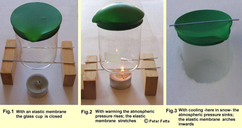
We make a small experiment which we can understand ideally and also technically. As in Fig. 1
to be seen, we stretch a rubber membrane e.g. an accordingly cut open balloon over a glas cup
- it should be fireproof! -
and lock thereby the air in the cup from the outside. Air in the cup has the same temperature and
same air pressure as the ambient air. This is the starting situation for the air in the cup in our little experiment.
If You warm up the cup and by this also warm up the air in the cup, You will observe that the rubber membrane
curves upward. Thus a pressure must have resulted from the heating up of the air in the cup,
which blows the rubber membrane up. See Fig. 2.
If now in a further step the whole cup is cooled down, so that air in the cup becomes even still colder
than the ambient air, then the rubber membrane curves inward. See Fig. 3. In this experiment I placed
the cup in snow. The outside temperature was -5 degrees C. Inside the cup thereby a smaller air pressure
adjusted itself than in the starting situation. If You bring the cup and air in it again to ambient temperature,
the starting situation resets itself, as it is seen in Fig. 1.
You cannot see air pressure, its effect however can be make visible by this rubber membrane.
For completely critical readers I took specially a transparent glass cup, in order to show that no further
aid is in the play. If a firm cover had locked the cup, we could make the change of the air pressure visible
only by a pressure gauge, or by a piston -see later.
This increase of pressure when heating up is it, which the Stirling engine converts into mechanical work. This must happen however always recurring; because otherwise we would have only one unique procedure, which we could use e.g. only for a unique lifting of a load. So that the increase of pressure takes place again and again however, and an engine can be developed, -You followers it surely already from above experiment- a cooling of air must take place in the same rhythm, in order to always come again to the starting point.
Now we make a first step, in order to come from the above experiment to a correct Stirling engine. We cut a tin open -a beer tin is suitable because of its very small wall thickness which is particularly well to heattransmission- and stick on it a cover made of aluminum. Within this cover a hole by 20 mm in diameter is bored. Into this hole we set a piston e.g. for plastic. If hole and piston are worked very well precise, so that the piston can be easily moved, but, no air escapes from the box besides, we can repeat the above experiment with this tin.
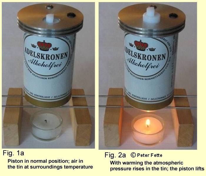
Here the increase of pressure causes as a result of the warming of the air that piston moves upwards
-we will call him now the "working piston" - Fig.2a.
If we blow out the candle, the working piston after cooling the air in the tin again takes the start position.
If we do the cooling even further and put the tin into snow, then the working
piston would be dragged even further in the cylindrical drilling of the lid, like in Fig.3 the elastic skin
on the glass cup arches inwards.
Now one could go, and provide the working piston with a crank gear and flywheel to make a rotating motion
from the up and down movement of the working piston. If one warms up the tin and cools it after the warming up,
one would already have an engine. Nevertheless, this would be uneconomical and very slow because here not only the air,
but first the whole tin must be heated and completely be cooled again. This interplay between warming up
and cooling the air is afflicted with a certain sluggishness, and this costs time.
We learn from the above experiments that one needs 2 mechanisms -heating and cooling-, in order to get increase
of pressure and decrease of pressure in a closed air space, in order to move thereby a working piston.
Nevertheless, between these 2 facilities, heating and cooling, there must be something more that
arranges the air to be in quickly returning rhythm sometimes hotly sometimes coldly in the machine.
The Scottish priest Robert Stirling worried about relief of the works
in the stone quarry, and constructed a safer hot air engine to replace
the (at that time) dangerous steam engine, had a brilliant inspiration:
One would have to create separate hot and cold zones in the machine and push the air with an "air mover"
sometimes fast in the hot and afterwards again fast into the cold area of the machine,
so that if the piston should do work, the air is predominantly in the hot area and causes the increase of pressure,
and, if the working piston should go back to its starting position predominantly air exists in the
cold area to cause the pressure sinking helpful for it.
In the Stirling engine named after him a "displacer piston" takes over this task of an "air mover".
What is the purpose of the displacer piston?
Next we insert this displacer piston, which can be moved up and down by means of a thin rod, which leads in the center of the cover into the beer tin. This implementation of the thin rod by the cover must be low-friction and also close, without air can escape from the tin or come in here. The diameter of this displacer piston should be clearly smaller than the inside diameter of the tin, so that air, if one moves the displacer piston up and down, can pass through the gap betwen inner wall and displacer upwards and downwards. See Fig. 4 (the "tin" is here and in the following pictures for more understandable representation a transparent glas tin.) The displacer piston is not a piston in the usual sense, but as his name already says, a "displacer" which edges out air from a part of the tin along itself in the other part of the tin with his movement. We will call him from now on the displacer. Our working piston remains in the tin like in the picture above.
Now follows an important experiment:
We warm up the tin below and cool it "at the same time" on top in the area of the lid
and the working piston. In the beginning the displacer is on top. See Fig. 5 on the left.
Now we know that pressure rises, and that the working piston -like already seen in Fig. 2a- moves itself upwards.
If we now move the displacer down, so that the warm air is pushed along it upwards, then the air can be cooled there.
We observe that a short time later, after the displacer
is below, the working piston also moves down.
We can repeat this up and down from the working piston steadily, we only need to move the displacer
up and down to it.
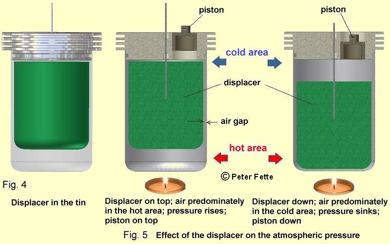
We have firmly established now 2 temperature zones in the tin, with simultaneous warming up in the lower
area of the tin and the cooling in the upper area, and as soon as the air is very completely in one of these
temperature zones, a suitable pressure appears.
Only by the effect of the temperature on the air the pressure is raised in the tin or is lowered.
Well noticed, the displacer is not a piston like in an air pump which can compress and suck in
the air.
The displacer cannot transfer work to outside, on the contrary it needs
work from the outside to move, and so the displacer should also be very
light; then the movement of the displacer requires very little work;
completely in contrast to the movement of a piston in an air pump. I have produced this displacer of the very light
and at the same time steady material Styrodur.
We do not have a revolving machine till present yet.
But now You have got to know about the thermal properties of the air, and You know about the effect of the
displacer in the machine. Within the Stirling engine the displacer is a very important equipment:
The gas pressure is lowered or is raised by pushing the air from the hot into the cold area of the engine and vice versa, so a piston can do work.
From the up and down movement of the working piston to a rotating motion
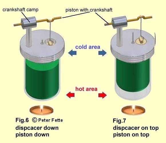
It would be usefull to couple the working piston, as on top already mentioned, to a crankshaft
to make a rotary movement from the pressure driven up and down movement of the piston.
For this we connect the working piston by a connecting rod to a crankshaft, which is made from a thick wire
like shown in Fig. 6.
Now by the up and down movement of the working piston the crankshaft turns a little.
But also now we still have no engine; since till present we have to move ourselves the displacer.
If we do this, we can observe that the working piston constantly lifts itself and lowers and turns
the crankshaft thereby. However, a complete revolution does not make the crankshaft yet.
If we would build the machine, as it is described untill present, and exactly observe, we see that the
piston does not reach the dead points belonging to the crankshaft. (Even if it is shown ideally
in the pictures to Fig. 8 !)
(Besides said: If we switch off the steady heating and cooling, and wait to surroundings temperature
in the tin, and we then lift the displacer up and down, the working piston does not move. It stops in the position
which he has taken after the waiting period. This must be like that; since the air then everywhere in the tin
has the same temperature and the same pressure no matter whether the displacer is moved or not.)
What is still missing?
Now, we must find a mechanism, in order to couple the displacer to the rotating motion of the crankshaft;
and we must create a further device, which makes it possible to reach and overcome the dead points of the piston
for a rotating motion. How we reach this, we will get to know in the both next chapters.
Crank gear with working piston and displacer
are important elements of the complete Stirling engine. After what is said up to now, we know that the up and down movwement of the working piston to transfer strength on the crankshaft is released by the position of the displacer.
If we move the displacer up and down, we recognise that after a certain temporal delay the piston and with it
the crankshaft also moves. This is due to the fact that the air needs time to warm up itself or
to cool off. See moreover the chapter
The heat transfer to the working fluid.
Now we can imagine ourselfs to let the displacer electromagnetically steered jump up and loose
and to keep it in every final position so long, until the working piston has reached this final position too
-on top or below. This would be even good, and with a flywheel -see the next chapter- on the crankshaft we would
have built almost an ideal Stirling engine!
Then this displacer control should function in the ideal state as follows:
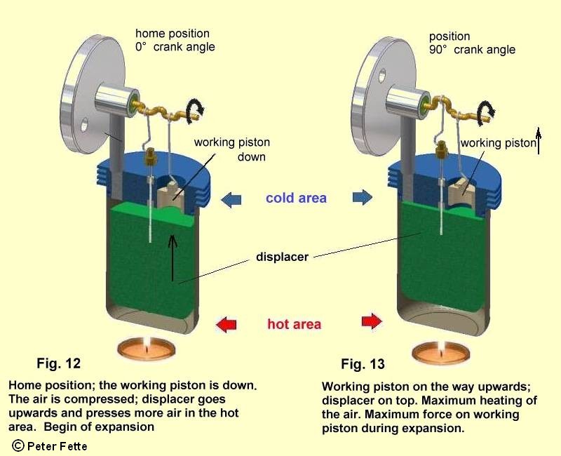
If the working piston is below, and should move upwards, the displacer has quickly to go up; then all the air reaches in the hot area, it is warmed up, the gas pressure rises, the air volume expanded, that becomes visible by the movement of the working piston upwards; the crankshaft turns.
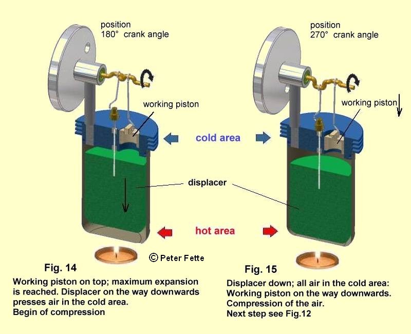
The displacer must remain as long in the upper position, until the working piston arrives on top. Then the displacer should shoot up down and push the air from the hot area into the cold one. In the lower position the displacer should likewise stop for a while again. The air cools off, its pressure sinks and the working piston moves down due to the starting contraction. The crankshaft further turns.
If the working piston has come below the play begins anew, again first with the high-level quickness of the displacer and the displacing of the air from the cold area into the hot area.
This kind of displacer movement is called "discontinuous displacer control";
the displacer movement does not run continuously to the working piston movement, it is marked by
shut down and shut upwards. I mention the discontinuous displacer control here to make clear the ideal
impact of the Stirling engine. The reader with some knowledge in thermodynamics may read for deepening his
knowledge the explanations in the report
"The Stirling process from thermodynamic view" (until now in German)
Indeed, the real Stirling engine which we want to get to know here must enter some compromises especially
into relation on the discontinuous displacer control. Since with a very quick movement and
deceleration very high forces on the ideal displacer hit, and would destroy it soon also if it
has only low mass.
A nearly discontinuous displacer control is realized in the slowly running flat disk Stirling engine of Ivo Kolin.
[1],[3]
in these two books is also presented a technical drawing of this flat disk Stirling engine.
Here however we look for a simpler mechanism, and try to connect the displacer continuously with the
rotary motion of the crankshaft.
One could receive a continuous displacer control, with a 2-nd crankshaft to the tin and couples it
"suitable" with the displacer and the 1-st crankshaft.
Nevertheless, it is easier to take for it the quite available crankshaft, and to connect a connecting rod
with the displacer and to couple this connecting rod suitably to the crankshaft.
But how, what is "suitable" here?
It was stated above that the movement of the working piston takes place in a certain temporal disalignment to
the movement of the displacer. If we want to couple the displacer to the already existing crankshaft, we must
transform this temporal disalignment into a crank angle shift.
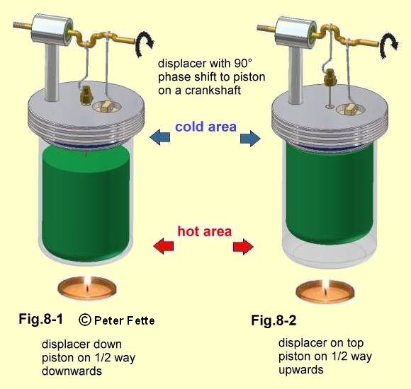
One can experiment here, it is, however, optimum to let prehurry the displacer
around a shift angle of 90 ° in rotation direction. Then a part of air has already reached in the hot area if the
working piston is below, and can warm itself up. The pressure starts to rise and presses the working piston
upwards.
For this we bend the thick crankshaft wire now in such a way that in a shift of 90 ° to the working piston movement
a connecting rod can be attached, which is connected about a joint with the displacer. See Fig. 8-1 and Fig. 8-2
(Why this should be like that, is to be explained at this point too complicated. Here I recommend to readers with
foreknowledge to read the report
"The Stirling process from thermodynamic view" until now in German.)
The flywheel for the rotating motion
Till present the machine does not work yet properly. If you heat the machine, it will stop near the uppermost
working piston position. This position is nearly reached, if the crankshaft in Fig. 8-2 in
the indicated rotation direction would be turned nearly approx. 90 degree further. Besides, we feel quite clearly
the strength which the working piston exerts upward with its movement on the crankshaft.
To receive a continuous rotary movement, nevertheless, the crankshaft must get a flywheel.
The flywheel is another very important element of the Stirling engine.
Without flywheel no single acting Stirling engine would be able to work.
Why?
Now, our real Stirling engine brings us its benefit work only in a small part -approx. 1/3- in its crankshaft
rotation. In approx. 1/6 rotation the engine brings nothing and needs also nothing, here the friction
losses and the positive forces rise mutually. But during approx. a 1/2 revolution the engine needs even energy.
Why is that thus?
In reality the cooling of the machine is not sufficient enough to lower the gas pressure so far in
the machine -as shown in Fig.5_right- that the working piston moves by itself into the lowest
position; since, because of the temporal sluggishness of the heattransmission, the air reaches not fast enough the
surroundings temperature, when cooled in the cold area of the real engine . This would be one cause.
Secondly:
If the displacer is down, it does not wait construction dependently, until also the working piston is down,
but it lifts itself again according to the 90° of phase shift of the crankshaft - see Fig. 8-1.
Is however the working piston down -Fig. 9- , then the displacer already is the half way upward,
and a hot air volume, which must be considered now, causes that the total pressure is still higher in the machine,
than it would be desirable for the lower position of the working piston.
Thus the cooling does not contribute completely however nevertheless somewhat to the downward movement of the piston.
Even with an ideal discontinuous displacer control -see above- we will receive no complete rotary movement without a
flywheel .
(The reader with knowledge in thermodynamics can read in the report:
"basis for computing the heat flows, work output and dynamics of
an a-type Stirling Engine" how the gas pressure
in the machine is to be calculated by the program "STMOT2". Both in German until now)
One speaks of the compression of the air in the phase of the downwards movement of the working piston.
Here it is where the real engine needs additional strength to press the working piston completely down.
And this strength repectively energy is delivered by the turning flywheel. Fortunately the energy, which is taken away
thereby from the turning flywheel, is smaller than the energy, which the engine supplies and transfers to the flywheel
in its operating phase, and therefore the engine can further turn.
If the flywheel is heavy enough, one will not even be able to see that, every time the working piston is pressed
downward the rotating motion a little is slowed down.
A further important realization follows from this:
One must set in motion the flywheel first of all, so that the Stirling engine comes to way.
The simple Stirling engine needs an assisted takeoff from the turning flywheel!
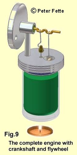
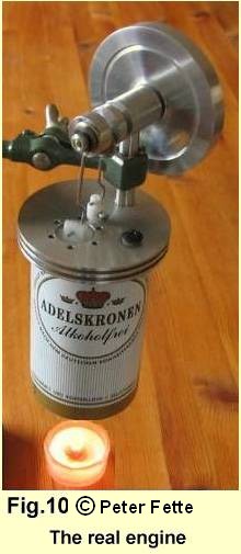
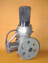
Now with the flywheel the Stirling engine is complete. This is the
b-type Stirling engine.
Fig.10 shows the finished beer tin Stirling engine with a crankshaft running in ball bearings.
The crankshaft was balanced with the hole in the flywheel. Click into this picture to see a short video of
the running machine. Thereby You will see that the machine is to be driven with the warmth of a cup of tea.
This engine may also be driven by solar energy. This shows a small reconstruction of the tins bottom. Look at
Fig.22 in the capter: The heat transfer to the working fluid
A similar engine, but built more compact, which can even be driven by the warmth of a hand, is described in his book
with technical drawings and reproduction advices by Dieter Viebach [6].
The crankshaft of the built machine is divided because of the use of ball bearings.
Working piston: stroke = 8 mm; diameter = 20 mm; length = 14 mm
Displacer: stroke = 15 mm; diameter = 60 mm; length = 70 mm
Construction manual for this machine for personal use only on inquiry about email in:
We observe 1 revolution of this b-type Stirling engine after Fig. 9
Fig.12 is identical with Fig.9, however, represented here on a cross section for a better presentation of the positions of displacer and working piston. Fig.12 shows the starting position at the crankshaft angle 0 °. In the following 3 pictures the machine has rotated further always 90 ° crank angle. Then the machine reaches the starting position again like in Fig.12.
Further type of the Stirling engine: the a-type Stirling engine
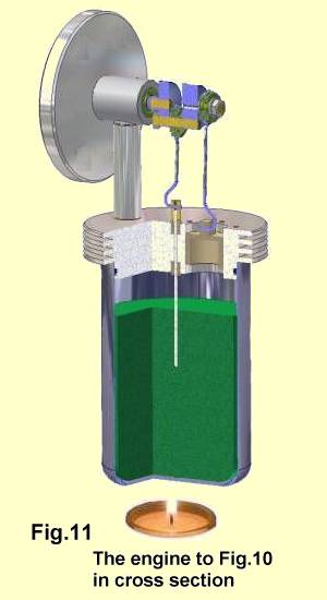
Fig.11 shows the so-called b-type Stirling engine, which is characterized by that its displacer and its working piston are accommodated in one space. The b-type Stirling Engine is a 1 cylinder machine. This engine is built for small to middle power. Besides there is the 2-cylinder 2-piston machine, that is the so-called a-type Stirling engine, which is built for middle to large power. Since this Homepage reports of the new development of a quadruple working a-type Stirling engine, also the function of this engine type is to be discussed. Fig.16 shows the most important details of the a-type engine.
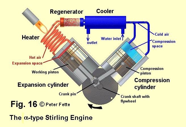
In Fig.16 we see two cylinders standing right-angled too each other, the expansion cylinder and
the compression cylinder. Their pistons and their piston rods are working on a common crankpin.
Because of this 90 ° arrangement of the two cylinders this a-type
Stirling engine is called the "V"- engine. The crankshaft is not well visible in
this picture. This engine also needs a flywheel. At the left cylinder head a heater is attached,
here represented by a flame and a bundle of tubes. The right cylinder head is cooled, before its
cylinder head a cooler is connected. The other connecting piece between the cooler and the heater is the
so-called regenerator, whose meaning we discuss further down.
With a lot of a-type Stirling engines the working cylinder is
not heated itself, but as it is shown, between the cylinder head and the Regenerator a separate
heater is set, like in Fig.16. This heater exists of many thin tubes connected to a bundle.
The air flows through the heater tubes into the expansion cylinder and is heated up thereby. The meaning of the heater is
described in the chapter The heat transfer to the working fluid. The cooler also exists of
many thin tubes and is surrounded by a water jacket for cooling the air in the tubes.
Also in this Stirling engine the heating and the cooling occurs like with the b-type
Stirling engine at the same time. We recognize that
there is no "displacer" within the a-type Stirling engine.
The function of this motor type is to be described like above the b-type stirling engine at 4 crank angle positions. We will see how both pistons push the air at the right time in the cold or in the hot cylinder of the a-type engine, so that the machine can do benefit work:
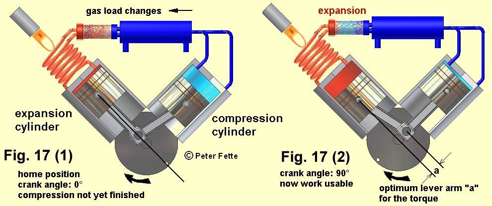
Fig.17 (1) is the starting position for the explanation. The piston of the expansion cylinder stands in the upper dead center. In this position the crank angle of 0 degrees should be defined. Most air is in the cold compression cylinder. Now the marked rotation direction can be maintained only by the rotation energy of the flywheel. (If a stop would be in this position, then the pressure on the piston of the compression cylinder would set the machine in motion exactly against the marked rotation direction - however this only for approx. 3/8 revolution. See also the following explanations to Fig.18)
Fig.17 (2) rotations 1/4 further: Crank angle position 90 degrees:
An exchange of the air from the
compression cylinder and cooler over the regenerator has taken place into the expansion cylinder.
Now in the expansion cylinder this mass of air is heated up, and, as we know from the above experiment,
the gas pressure has strongly risen by the heating in the machine, it is considerably higher than
the pressure in the machine at the starting position in Fig.17 (1).
In both crank angle positions (Fig.17(1) and (2) ) the air volume is as big in the machine, only the now bigger
mass of the air in the hot expansion cylinder has caused the increase of pressure -Fig.17 (2).
Now the force which works due to this high pressure on the piston in the expansion cylinder can bring an optimum
torque on the crankshaft. This is done in the marked rotation direction with the maximum lever arm of "a"
-see in Fig.17 (2).
The pressure on the piston in the compression cylinder is the same as on the piston in the expansion cylinder
-once apart from the small pressure losses in the heater, cooler and regenerator-.
The right-angled arrangement of the two cylinders causes a
phase shift of 90 degrees in the motion of the pistons. That means: the piston of the compression cylinder
has in each case 90 degrees later always the same position in its cylinder in the marked rotation direction like
before the piston in the expansion cylinder. Thus with 90 degrees of crank angle -Fig.17 (2)- now the
compression piston is located in the upper dead center. But the equal large force on
this piston due to the same pressure in the machine does not have a lever arm in this crank angle position,
in order to bring a torque on the crankshaft. In this angle position thus alone the optimal effective force
of the expansion piston affects the crank gear.
Further:
 atmospheric
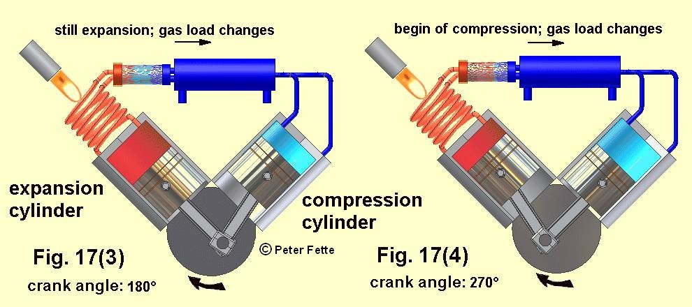
Fig.17 (3)
In this further 1/4 revolution the forces on both pistons brought profitable torques on the crankshaft.
Crank angle position now 180 degree. The air volume became larger
in both cylinders due to the downward movement of both pistons. Indeed, by this expansion the air
pressure has sunk, profitable work has been still done up to here. The flywheel energy has clearly been
raised by the rotation from crank angle 90 Fig.17(2) to crank angle 180 Fig.17(3).
From now the air mass moves in the compression cylinder.
Fig.17 (4) In the next 1/4 rotation from position (3) to (4) to crank angle position 270 degrees the air mass grows in the compression cylinder. The force on the cold piston could contribute on its way still to the benefit work from (3) to (4), however, partly against the force on the expansion piston, so that already after half a way from (3) to (4) the flywheel energy must be tapped to the maintenance of the rotary movement, since in (4) the compression has already been started. By the way, exactly on half a way from Fig.17 (3) to Fig.17 (4) - with the crank angle position 225 degrees - the maximum air volume is reached. See Fig.17(6) and in addition also the explanations to Fig.18b.
In further 1/4 revolution, in which the entire air volume is compressed under cooling, we come again to the starting position Fig.17 (1). For this range of the revolution (4) to (1) energy is consumed, which, as we already know, is taken from the flywheel. Fortunately, the benefit work of course is bigger with this Stirling engine than the energy which must be tapped to the compression work by the rotation energy of the flywheel.
2 important differences of a-type of stirling engine to the b-type stirling engine:
The displacer in the b-engine moves in a space of constant volume. See Fig. 11. The whole gas volume is changed in the b-engine only by 1 working piston. With the a-type Stirling engine both pistons influence the whole gas volume. A substantially bigger compression relation Vmax/Vmin can be thereby reached here, what enables the a-type Stirling engine to produce higher power. In addition you read closer explanations in the " The Stirling process from thermodynamic view"
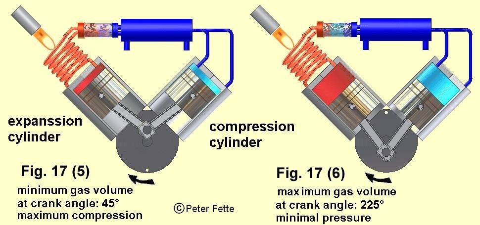
Another important difference to the b-engine is the crank angle position where minimum- and the maximum gas volume in the a-machine is reached. See the above pictures Fig.17 (5) and Fig.17 (6). Besides noticed, these crank angle positions are valid only, if both pistons have the same diameter.
Even if it should to be the actual goal of this description completely to get along without formulas and diagrams,
then it appears to me for some readers useful to discuss also the progression of the torque in this
a-type Stirling engine and to represent as well the dependence of the gas
volumes in the expansion and compression cylinder and the progression of the entire gas volume including all dead volumes
as well as the gas pressure as a function of the crank angle for 1 revolution of the machine.
Reference besides:
The diagrams in Fig.18a and Fig.18b have been calculated for the a-type Stirling engine
with the diameters of both pistons are equally large. Friction losses as well as the pressure losses in the gas flow
have been accepted in this computation as neglectable small.
Fig. 18a :
The force on the piston of the expansion cylinder causes a torque PFE and the force
on the piston of the compression cylinder causes a torque PFK.
(By the way: both forces are equally large because of the same pressure and the same diameters of both cylinders.
The different progressions of the torque curves touch here from the lever arms
which change with PFE sine-shaped and with PFK cos-shaped.)
Both torques together result in the outward effective total torque DREHM.
Within the range of crank angle position 45 to 225 degrees the total torque DREHM is positive;
here the benefit work is done, which can be used, e.g., for the rise of the rotation energy of the flywheel.
(Already mentioned, the friction losses were neglected with this calculation.) in the other crank angle positions the whole torque
DREHM is negative. Here a part of the rotation energy is diminished.
But luckily this energy consumption is lower than the benefit work, so that with every other rotation the speed
and with it the rotation energy increase if no consumer should be driven by the machine. If however a consumer is driven
by the engine, this can win with a steady speed just the difference between positive and negative
torque as a benefit work.
In Fig. 18b the gas volumes and the gas pressure P are applied for 1 rotation. VE is the gas volume in the expansion cylinder and VC is the gas volume in the compression cylinder. VG is the whole gas volume including the regenerator volumen and all other dead volumes in the machine. For the maximum gas pressure P approx. at 45 degrees of crank angle the gas volume VG has a minimum. And with a maximum gas volume VG at 225 degrees of crank angle the gas pressure P has its minimum.
Remarkable:
Expansion work is done from 45 - 225 degrees, while compression work must be applied from 225 to 45 degrees beyond a full rotation under tapping of the rotation energy of the flywheel. The benefit work of the engine, thus the work which can be supplied to a consumer -or serves the increase of the rotation energy of the flywheel, if no consumer is connected, this benefit work is the difference between expansion and compression work.
I have described in the previous and in this chapter the procedures in the real Stirling process. This may confuse some readers with some knowledge in thermodynamics if they do not differentiate correctly between the the real one and the ideal Stirling process. For deepening their knowledge these readers like the site: "The Stirling process from thermodynamic view" as well as "basis for computing the heat flows, work output and dynamics of an a-type Stirling Engine" with the program "STMOT2" on this homepage.
A very good animation of the a-type
Stirling engine with correct thermo-dynamic relations and some diagrams, Michael Abendschön
(e-mail:  ) has made as an Adobe flash player application with
some engine datas, which I calculated with my program "STMOT2".
I am connected to him to big thanks to be able to publish his work here. This animation becomes visible in browsers,
which can process Adobe Flash-player Plugins. Now the Adoabe flash-player is no longer supported.
I now transport the flash-data into a powerpoint application. You can navigate the animation by the > < cursor keys
Below You can see a picture and diagrams from this animation.
You see here the 45 degree crank angle position of the a-type
Stirling engine, as to find it in Fig.17(5).
) has made as an Adobe flash player application with
some engine datas, which I calculated with my program "STMOT2".
I am connected to him to big thanks to be able to publish his work here. This animation becomes visible in browsers,
which can process Adobe Flash-player Plugins. Now the Adoabe flash-player is no longer supported.
I now transport the flash-data into a powerpoint application. You can navigate the animation by the > < cursor keys
Below You can see a picture and diagrams from this animation.
You see here the 45 degree crank angle position of the a-type
Stirling engine, as to find it in Fig.17(5).
Below the engine you see a P-V diagram of the real process
(the ideal Stirling process is marked sketched in the same volume borders: VGmax = 800 cm3
and VGmin = 330 cm3).
A red mark point stands with the minimum whole air volume VGmin this corresponds to the crank angle position
of 45 degrees.
On the right beside the P-V diagram you see a diagram in which the air pressure P
and the whole volume VG are applied as functions over the crank angle.
(To the definition of the whole volume VG
see above the Fig. 18b.) In this and both other diagrams, if the animation is started,
moves a red sketched line in which You can read the instantaneous crank angle in the diagrams abscissa;
this instantaneous crank angle additionally is written below the crankshaft in the
scetched a-type engine.
Completely on the right the function of the benefit work is to be seen versus 1 crankshaft rotation.
The benefit work reaches its maximum value if the expansion is finished and the whole air volume also has its
maximum at 225 degrees of crank angle. The resultant benefit work of 1 rotation which can be delivered from
the crankshaft outwardly after deduction of the compression work amounts here to approx. 125 Newton * meter.
(This is read in the diagram at 360 degrees of crank angle)
This is approx. 0,000035 kWh; with 500 rev/min this would be a shaft power of approx. 1 kW.
The 4-th diagram is important where the air mass distributions are to be seen in both cylinders and in the
regenerator as a function of the crank angle. The air masses in the cold and hot dead spaces are assigned
in each case to the air masses of the cold or hot cylinder. We see that the air masses are steadily in motion.
Nevertheless, an air change from cold to hot is considerably quicker achieved (approx. in 90 degrees)
as vice versa the air changes from hot to cold for which nearly 270 degrees of
rotation are needed . Above all the readers who knew so far only the ideal Stirling process may realise
the reality of a constant gas change. In the ideal Stirling process the expansion takes place after the gas masses
completely change from cold to hot; and the compression takes place after the gas masses completely
change from hot to cold. However, no real machine is conceivable with which these 4 processes can run off as
successively. In real machines these processes overlap.
Within Stirling engines of the a-type nevertheless it is provided on
account of the phase shift in the movement of both pistons, that the working gas during the expansion stays
predominantly in the hot regions of the engine, and that it stays in the cold regions of the engine predominantly
during the compression phase.
Also with the b-type Stirling engine with more continuously
displacer control -see Fig. 11- it is in such a way. And also here a constant air mass
change takes place. Because within the b-engine only 1 piston works,
the beginning of the expansion and the beginning of the compression is rather to be recognized
in the actual dead center positions of the piston. see on top.
Click into the picture to start the powerpoint animation, and navigate the animation by
the > < cursor keys
In the P-V diagram, You will see "middle" temperatures which are faded at places on the curve
which correspond to the 0, 45, 90, 180, 225, 270 and 360 degree crankshaft angle positions.
The meaning of these temperatures, I discuss in:
"The Stirling process from thermodynamic view"
as well as in "basis for computing the heat flows, work output and dynamics of
an a-type Stirling Engine"with the program
"STMOT2" on this homepage.
The diagrams Fig.18a, Fig.18b as well as the diagrams beside the animation have been calculated
with the program STMOT2. You find the input data for use with STMOT2 in:
Sample Simulations with diagrams for the heat-process and the dynamic of
a-type Stirling engines.
There are different implementations of the g-type Stirling engine. M.Werdich [3] has described it in detail.
You see 2 implementations of the
g-type of Stirling engine in Fig.30 and Fig.31.
Fig.30 reminds of the a-type Stirling engine see Fig. 16
and Fig. 31 reminds of the b-type see Fig.9.
However, the 2 characteristic differences of the
g-type engine to the a-type and to the
b-type Stirling engine are, that a displacer works in a separate cylinder
-in a displacer cylinder-, and 2'nd from the cold area of this displacer cylinder the gas and also the gas pressure
reaches under the working piston of the working cylinder by a connecting tube.
One can form the displacer just like shown with the b-type
in the above picture Fig. 31.
(To the impact of the displacer see the chapter:
What is the purpose of the displacer piston?) We want to get
to know here, however, another kind of the arrangement of the displacer, as it is shown in the above
picture Fig. 30.
The displacer is here a piston which lies closely in his cylinder, and with his movement he edges out
the working gas - we take air again- according to the movement direction through the heater and through the regenerator
from the upper hot area VH into the cold area
VK, or vice versa with his movement downwards he
edges out the air from the cold area
VK through the regenerator and the heater into the hot area
VH.
The connecting tube from the cold area VK
to the working cylinder goes here, in addition, still through the cooler.
Do not compare this displacer piston with the expansion piston in the
a-type engine in
Fig.16; since in the g-type engine the displacer piston does
not perform useful work and no compression work.
As described previously, he should move easily, and only move the air bidirectional and have so little friction
as possible.
You see a specific feature, a "heat top" in the hot area VH above the
displacer piston, which is necessary for
engines of higher power at high temperatures. The displacer cylinder is cooled in its cold
area VK because the sealing gaskets of the displacer piston must remain effective.
Now the supplied warmth at top of the displacer cylinder of course should not be led away immediately again
from the coolant, therefore, a thermal distance is necessary. This distance is realised by lengthening
the displacer cylinder and by the "heat top" above the displacer piston.
Also in the a-type Stirling engine such a "heat top" and a
cooling is necessary in the area of the
working piston. One may forgive me, that I have not considered this in Fig.16 and in Fig. 17.
Also with this machine we again want to pursue 1 rotation in 90-degree steps. First would be still said that it is also optimum here to let prehurry the displacer compared with the working piston by an angle displacement of 90° in rotation direction.
Fig.37(1) shows the starting position of our consideration. In this position the crank angle 0° shall
be defined. The displacer stands in the upper dead center. The gas volume
VH in the hot area has become a minimum.
(VH = 0 would be ideal, however,
this will never be reached in a real machine.)
The displacer had pressed the hot gas through the regenerator into the cold area
VK.
Besides, the before cold regenerator has taken up the heat energy of the hot gas to a
great amount in itself. This is indicated by the red colouring of the regenerator.
In the next chapter the regenerator is described closer.
The gas volume VK in the cold area of the displacer is a maximum
in this position. The piston in the working cylinder is on half a way upwards and compresses the working gas which is
also cooled with this compression. The machine gets the energy for the compression from the flywheel.
After 90 ° rotation the compression is finished in Fig.37(2), the working piston stands in the upper dead center. At the same time with the movement of the working piston the displacer piston has reached half a way down and has pressed a part of the cold air from VK through the regenerator and the heater into the hot area VH; gas load change from cold to hot. Besides, the cold air already warms up itself in the regenerator. The whole pressure in the machine starts to rise. Up to this position the machine needs power and gets it from the flywheel.
After an other 90 ° rotation we come to crank angle position of 180 ° to Fig.37 (3). The displacer piston has come down and has pushed the air from the cold area of the displacer cylinder through the regenerator and the heater into the hot area of the displacer cylinder. Now VH has reached its maximum. Besides, the regenerator has been unloaded i.e. he has got cold. The whole pressure of the working gas in the machine has further risen; the piston in the working cylinder now performs usefull work; besides, the flywheel energy increases.
In Fig.37 (4) the gas load change has reinstated after another 90 ° rotation; this time from hot to cold. The regenerator has been loaded partly again. Up to this crank angle position of 270 ° useful work has been done. The working piston stands in the lower dead center. From now the compression of the air starts in the working cylinder. Then after other 90 ° rotation the source state is reached like in Fig.37(1).
The Stirling engines, as far as we have discussed them up to now, also work without a regenerator rather useful.
However, we can think about the efficiency of these machines. Efficiency means:
How efficient in the Stirling engine is the conversion of heat energy into mechanical energy? Or: How can we
lower heat losses?
One method would be to isolate the hot parts of the machine against the heat radiation.
This is quite important, however, in the machine itself, still in its working process there is a possibility for a
better use of the input heat:
Always when the air from cold is pressed into the hot area, by the movement of the displacer
in b-type or g-type machines
-see Fig. 5-type and Fig. 31 and Fig. 30-
or by the piston movement in the a-type machines, the air must be reheated at
first, before it can do work by further heat supply during expansion. And reverse, if the air from hot is
shifted into the cold area it should be already precooled, before with further cooling the compression can occur.
If we could store the energy, which must be added to the air on one way and
which must be delivered from the air on the way back, in a suitable buffer
and if we could load it at the right moment again, then the engines efficiency would be better.
This energy intermediate storage is the task of the regenerator. As its name already says, it should regenerate
something. Namely, it should regenerate the state "hot" again if the air comes back from cold into the hot area,
and vice versa it should regenerate the state "cold" if the air from hot is pressed into the cold area.
With the a-machines we can realize a regenerator as a piece of pipe between
compression cylinder and expansion cylinder in which sits a thick-packed wire mesh, see Fig. 16.

The effect is the following and should be made clear by red about orange up to and blue colouring in Fig. 20:
If the air of the hot area flows out coming into a cold Regenerator, it delivers its heat to the wire mesh.
Besides, maybe the air does not get cold completely on such a way as by further cooling in the cooler,
but, at least, a considerable amount of heat energy now is in the wire mesh.
On the way back from the cold area into the hot area with the
b- and the g- machines, (or on the way from the compression- into
the expansion cylinder with the a-machines), the cold air can fetch back a large part
of heat from the wire mesh, and therefore needs to be warmed up in the heater or in the expansion cylinder no more from
the quite cold state. On this way back the regenerator cools off again.
Then it will have to be supplied less heat during the benefit work tact respectiv during the expansion, than without the
regenerator!
We can define the efficiency of a regenerator in such a way, that we set the temperature difference from the hottest
to the coldest place in the regenerator into relationship to the maximum temperature difference between the hottest
and coldest temperatures in the machine.
Tim Lohrmann (look at his German page:
http://www.stirling-und-mehr.de/Der_Regenerator.html )
has proved a nice everyday example of a regenerator by
comparing it to a scarf:
Walk around outdoors in very cold winter weather, but breath through a
thick scarf and then try the same without a scarf. You will notice the
air you are breathing is warmer with the scarf than without.
When you breath out through the scarf your warm breath warms the fibres
of the scarf. When you breath in, the warm fibres heat the cold air. This
process is exactly the same as a regenerator, it is a regenerator.
It is saving heat which would be lost and then giving the heat back, you
get something for almost nothing, it is slightly more difficult to breath.
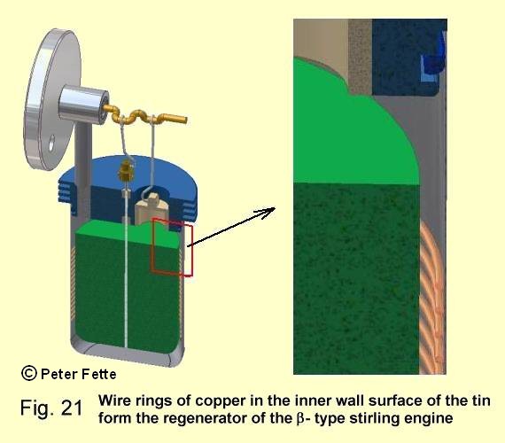
With the b-type stirling engine, which we discussed above,
or with the
g-type stirling engine after Fig.31, we can imagine a
regenerator as follows: At the inner wall surface of the tin -see accompanying picture, are attached copper rings
in small distance on the length of the displacer; so that the displacer does not get into contact to these rings
while pressing air through the gap as described above. If the displacer goes down from above, he presses hot air upwards.
The heat energy of this air is passed gradually to the rings. The lowest ring will be hottest thereby.
Vice versa if the displacer goes upwards from below it pushes cold air along the rings down into the hot area.
Now thereby the air can warm up itself by the rings and so it already reaches preheated downward.
The rings were cooled by this.
The uppermost ring is the coolest. In this way the rings work like a regenerator.
However, with the b- and g- machines
the whole displacer can also exist of a thick-packed wire mesh in which the air glides past.
The heat transfer to the working fluid
In the b-type machine -see Fig.10- the tin is hetated from below. The thin metal leads the heat fast in the inside; here it is transfered on the enclosed air. In the upper area of the tin the working gas is cooled. Very similar is the heat transfer within the g-type Stirling engine in Fig.31.
In the a-type Machine to Fig.16 the working gas (e.g., helium)
is warmed up in a heater which is set before the working cylinder. This heater exists of many thin tubes.
Similar is the heat transfer within the construction of the g-type Stirling engine after
Fig.30.
On the cold side of these machines a cooler is set before the compression cylinder (or working cylinder)
which also exists of thin tubes. Outside these tubes the coolant flowes around.
Why is the expansion cylinder not heated directly, or why is the compression cylinder not cooled directly
e.g. by a water coat???
It is important that the working gas in the expansion cylinder (or in the hot area) of the Stirling engine reaches the temperature of the heat source as quickly as possible, and that it is brought fast on coolant temperature in the compression cylinder (or cold area) if it is fast moved to and from between these both spaces.
The cold area should not be impaired by heat from the hot area. This demand is not well solved with the
b-type Stirling engine to Fig.9 und 10; since the
warm waste gases of the candle flame climb up, and reach therefore in the cold area; this, however, is in weakened form.
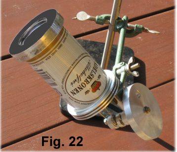
It would be better to turn the machine to heat it from above; e.g., with the solar heat in which one
solders a bigger copper plate on the ground of the tin. This should be blackened and turned to the sun.
Then the cold area would still lie in the shade. See accompanying picture Fig.22. (Here a ring of aluminum
was adapted to the ground curvature of the box. The ground of the box and the aluminum ring were blackened.
At working outside, it should be calm or a glass cylinder must be turned about the ground of the box.)
The heat transfer to a gas flowing at varying speed is a complex process; numerous scientific publications deal with this subject. I would like to call here only 4 -of some more- determining dimensions for this heat transfer; these are
- a well heat conducting wall material, that should be very thin,
- the surface for the heat transfer, which should be possibly big,
- a well heat conducting working gas; (air is worse, e.g., helium is much better; hydrogen leads the heat best of all)
- and a possibly "short way" for the heat transfer.
The well heat conducting wall material, the big heat transfer surface, and the well heat conducting working gas are
evident; the importance of a short way for the heat transfer may become clear in our 1-st experiment in
Fig.1-3. Here we wait quite a while, until -at warming the glass cylinder- the elastic membrane lifts.
This is not only due to the fact that glass is a bad heat conductor, but more at the fact that the
"way is surely long for the heat" to come from the inner wall surface of the glass cylinder up to middle.
If we could measure the temperature, we find out that the air temperature has risen near the inner wall very fast,
while it rises in the middle of the glass cylinder much more slowly.
That's why one does not heat and does not cool the cylinders directly in high power Stirling engines.
The thin tubes in the heater and in the cooler have a big surface, and the way for the energy transfer
in the tubes is short.
In the beer tin Stirling engine -Fig.10- the heat transfer is completely not so good, but,
because of the vortex motion of the air which happens by the displacer movement, enough air molecules get into contact
with the inner wall to make a sufficient heat transfer to the whole hot air space. We also do not want to achieve a
high power with this engine.
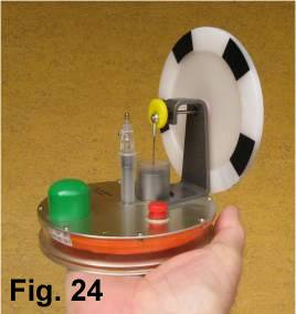
More optimally the heat transfer is solved at the "lowest temperature" Stirling engine made by Dieter Schager, Offenburg.
See accompanying Picture Fig.24. It is pursued with the warmth of a hand. 1 degree in temperature difference is already
enough to drive this small engine. The heat transfer surfaces exist of 2 aluminum plates of hand size;
between these plates the displacer moves, the airspace, and that is the "way for the heat transfer", is of short height.
are permitted:
1) If the Regenerator regenerates the air temperatures so nicely, why must then be cooled even further during the
compression tact?
2) and why must be heated up during the benefit work tact -the expansion- even further
if the air was brought by the Regenerator already on temperature?
Answer:
If I compress a gas, e.g., while inflating a bicycle tube with an air pump, then the air pump becomes in front
quite warm, and it is also rather strenuous to do this work. Indeed, the air pressure rises
additionally, as a result of the heating up during the compression work with the air pump, however,
this additional increase of pressure uses nothing to me afterwards; since in the tube this additional
pressure profit gets lost after a short time, when the surroundings temperature returned in the tube.
This additional pressure increase as a
result of the concurrent temperature rise with the air pump signifies only additional expenditure in work for me.
If I could press the air cooled with the air pump into the tube to come to my desired pressure in the
tube, then I need to do less work!
Otherwise with the expansion; here a further heating is wanted. Because here I want to have as for a long time as possible a high air pressure on the working piston. In principle pressure and temperature sink during the expansion of a gas in a cylinder with a piston. However, if I bring heat during this expansion additionally to the air, the pressure does not sink so strongly, and so can be performed more work!
An air pressure engine could perform more work, if the air is heated during the expansion. This is declared in more details in the site "The Stirling process from thermodynamic view"
This chapter will be translated soon (help needed)
Bei den bisher betrachteten Stirlingmotoren herrschte Umgebungsluftdruck in den Zylindern sowohl
oberhalb der Kolben als auch auf der Unterseite der Kolben, siehe Fig.16
(bzw. auf der Ober- und Unterseite des Arbeitskolbens beim b- Typ Stirlingmotor,
Fig.10).
Damit der Stirlingmotor mehr Leistung bringt, ist es nötig, dass mehr Gasmasse in ihm erhitzt und
gekühlt wird. Das kann man erreichen, in dem man die Zylinder grösser dimensioniert,
oder besser dadurch dass man den Druck des in den Zylindern eingeschlossenen Gases erhöht.
Readers with knowledge in thermodynamics will find more explanation in:
"The Stirling process from thermodynamic view" and in
"Basics for computing the heattransfer process and the dynamic of
a -type Stirling engines by the program STMOT2".
Both sites in German only.
Auch durch höhere Temperaturen im Erhitzer und durch stärkere Abkühlung des Gases auf der kalten Seite
kann die Leistung gesteigert werden. Doch das wollen wir an dieser Stelle nicht behandeln, sondern uns nur auf die
Drucksteigerung einlassen.
Bauen wir uns um die a-Typ Maschine nach Fig.16
ein gasdichtes Kurbelgehäuse wie es Fig. 38 zeigt. (Der vordere Deckel ist hier der Übersicht halber
weggelassen.)
Geben wir jetzt einen hohen Luftdruck in die Zylinder oberhalb der Kolben, dann
bewegen sich die Kolben sofort nach unten wie in Fig. 38 gezeigt, und die Maschine lässt sich
nicht mehr drehen. Selbst, wenn wir den Brenner einschalten, und das Gas im heissen Zylinder erwärmen,
kann die Maschine nicht angeworfen werden.
Das darf natürlich nicht sein!
Wenn wir aber auch das Kurbelgehäuse mit dem gleichen Luftdruck füllen, lässt sich die Maschine wieder drehen, sodass wir durch Drehen des Schwungrades auch die Ausgangsstellung Fig. 39 (wie in Fig.16 gezeigt) erhalten können. Schalten wir jetzt den Brenner ein, und werfen wir die Maschine an, wird sie arbeiten.
Was haben wir jetzt gewonnen gegenüber dem Zustand der Maschine in Fig.16 oder auch in
Fig.10,
wo im Ausgangszustand der kalten Maschine Umgebungsluftdruck oberhalb und unterhalb der Kolben herrschte ??
Dazu ein kleines Experiment:
Laden wir die Dose im kalten Zustand (20 °C) auf 5 Bar auf, und erwärmen sie wieder auf 100 °C, wird uns der
Druckmesser ca. 6,36 Bar anzeigen. Die Druckdifferenz (Druck im warmen Zustand - Druck im kalten Zustand) ist
jetzt mit 1,36 Bar erheblich höher.
Wir können also mit der Aufladung des Motors bei gleichen Temperaturverhältnissen eine höhere
Druckdifferenz gewinnen als ohne Aufladung.
Die pro Umdrehung erzielte Nutzarbeit des Stirlingmotors ist eine Funktion der
Druckdifferenz vor und hinter seinem Arbeitskolben; denn diese Druckdifferenz ist es, die letztlich den Kolben bewegt.
Diese Druckdifferenz darf jedoch nur infolge der Temperaturdifferenz zwischen heisser und kalter Seite des
Stirlingmotors entstehen (wie oben, beschrieben); das bedeutet, dass in der kalten Maschine,
wenn sie aufgeladen ist, zunächst ein Druckgleichgewicht herrschen muss bevor geheizt wird !! Das ist in der
Maschine Fig.39 der Fall, während in Fig.38 kein
Druckgleichgewicht besteht.
Readers with knowledge in thermodynamics will find more about this fact in:
"Basics for computing the heattransfer process and the dynamic of
a -type Stirling engines by the program STMOT2".
This site in German only.
Nun kann es aus konstruktiven Gründen nicht immer erwünscht sein, das Kurbelgehäuse mit hohem Druck
aufzuladen. Beim a -Typ SOLO-Stirlingmotor hat man sich
mit einem aufgeladenem Puffervolumen unter beiden Kolben beholfen, welches dem Hubvolumen entsprechend dimensioniert
wurde; die Kolbenstangen wurden gasdicht in das drucklose Kurbelgehäuse geführt.
Siehe das nebenstehende Bild.
Wenn man es ganz genau nimmt, dann erkennt man, dass im kalten Zustand dieser Maschine kein exaktes Druckgleichgewicht
besteht oberhalb und unterhalb der Kolben, weil ja der Querschnitt der Kolbenstange abgezogen werden muss von der
druckbeaufschlagten Fläche auf der Unterseite
beider Kolben. Die Kolbenstangen enden ja in dem drucklosen Kurbelgehäuse. Man könnte dieses geringe
Ungleichgewicht ausgleichen, indem das Puffervolumen und die Unterseite beider Kolben mit einem entsprechend
berechneten Überdruck aufgeladen wird.
Weil aber der Kolbenstangendurchmesser relativ klein ist gegenüber dem Kolbendurchmesser, und weil die
Erhitzertemperatur recht hoch ist (ca. 800 °C), und weil dieser Stirlingmotor mit einem el. Anlasser angeworfen wird,
kommt die Maschine dennoch in Gang.
Eine weitere recht elegante Methode den Stirlingmotor aufzuladen ist, eine doppelt wirkende Maschine zu bauen. Hier wirken 2 Teil-Maschinen auf die selben Kolben.
Readers with knowledge in thermodynamics will find more about this in
"Development from the Single Acting to a Twice Double Acting
a- Type Stirling Engine"
Bei dieser Maschine besteht ein absolutes
Druckgleichgewicht im kalten Zustand, weil die Kolbenstangen auf einen Kreuzschwingen-Kurbeltrieb wirken, der sich
in der Mitte der Maschine befindet.
Auch der "g-Typ Stirlingmotor" wie in Fig.30 gezeigt, kann aufgeladen werden. Ein Beispiel dafür ist der Viebach-Stirlingmotor ST05G Fig.28.
Wie ein "b-Typ Stirlingmotor" als doppelt wirkende Maschine aufgeladen werden kann, zeige ich demnächst auf dieser Seite.
The a-type Stirling engine works according to the same principle as
the b-type Stirling engine or
the g-type Stirling engine;
it causes the transformation of heat energy into mechanical energy.
This occurs while the pressure of a gas enclosed in the machine (e.g., air) rises under steady heating, and
therefore causes force on a piston. This force is delivered outwardly over a crank gear as a torque;
thus mechanical work originates as a result of expansion of a gas volume enclosed in the machine.
However, for a closed cycle (that is equivalent to continuous rotating motion) comes into this working process,
a part of the won work must be spent, in order to reach the starting situation again. This takes place via
compression of the gas up to the start volume. Here then the cycle begins again. The work necessary for it however
can be kept smaller by good cooling the air during the compression. The difference between expansion work and
compression work then is the usable work of the process, with which e.g. an el. generator can be driven.
We can from so far learning to note that the Stirling engine can perform all the more duty,
the more highly the temperature difference is between the hot and the cold side of the machine.
most important differences between the a-type, the b-type, and the g-type Stirling engine:
The displacer in the b-type engine and in the g-type Stirling engine moves in a space of constant volume. See Fig.11 and Fig.30 and Fig.31. The whole gas volume is only changed by 1 working piston, both in the b-type engine and in the g-type engine. With the a-type Stirling engine both pistons influence the whole gas volume. See Fig.16. The a-type Stirling engine has its minimum volume with the crank angle position of 45 degrees and the maximum volume at 225 degrees; see Fig.17(5); Fig.17(6) as well as the animation of the a-type Stirling engine. However, the b-type engine has its minimum volume at 0 degrees and the maximum volume at 180 degrees of crank angle position of the working piston. See in addition the pictures Fig.12 and Fig.14. The g-type engine has its minimum volume at 90 degrees and the maximum volume at 270 degrees of crank angle position of the working piston see Fig.37(2) and Fig.37(4).
In contrast to g-type engine the workrooms of the displacer and the piston
with the b-type Stirling engine may overlap; thereby one can realise
higher compression, and by this a higher power can be achieved.
In the b-type after
Fig.12 this can be done by a small lengthening of the connecting rod for the working piston; then the
piston in its lower dead center rises in the displacer space.
With some
g-type Stirling Engines the piston and the displacer have a common axis.
Some applications of the Stirling engine
Initially it was mentioned that the stirling engine can work with arbitrary heat sources. This fact makes possible a multiplicity of applications for this machine. A particularly interesting and environmentalpolitically very important application is the generation of electricity with solar heat.
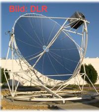
The heater of a high-level temperature - Stirling engine is put in the focus of a concave mirror.
Temperatures from more than 1000 °C can reach the heater here.
This mirror must be tracked to the sun in 2 areas.


Large solar thermal electric power plants using parabolic trough collectors are operating since 1985 in Southern California
USA. These are the SEGS units, in the beginning with 30 MWe, and now with some 100 MWe. In Europe we find newer types of
these plants at Almeria in Spain.
Within a parabolic trough mirror there is no focus but a "focal line"; so these mirrors must be tracked to the sun
only in 1 area. In parabolic trough collectors plants a pipe is located in the focal line of the mirrors which is
flowed through by a temperature-firm liquid.
This liquid is heated up to 450 °C and can be supplied to a stirling engine, as it is described in this homepage.
In the up to now established parabolic trough collectors plants the hot liquid is used for steam production.
A conventional steam turbine drives an el. generator in these plants; see [4],[5].
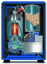
Further energy sources for the stirling engine are waste heat utilization (e.g. from the glass industry),
fermentation gas, biomass burn; here in particular the stirling engine of the company Sunmachine is to be mentioned,
which receives its driving heat from the burn from wood pellets. See accompanying picture.
It is very important for the stirling engine that the hot combustion gases, which reach the Stirling engines
heater do not contain fly ash, tar or other impurities, which can set off on the closely standing heater tubes
and so worsen the heat transition.
For the wood pellet burn Sunmachine solved this problem.
P.S.: I tried here to explain the function of the stirling engine as simply as possible and without formulas.
It is however important for deepening the understanding of the Stirling working process to have further knowledge
in thermodynamics and to read appropriate literature. For the computation of the crank gear and the flywheel
you need knowledge in mechanics.
For students of mechanical engineering with knowledge in thermodynamics additionally the side
"The Stirling process from thermodynamic view"
as well as
"basis for computing the heat flows, work output and dynamics of
an a-type Stirling Engine"
with the program "STMOT2" would be recommended in addition to this.
In [2] you find many details to the Stirling engine.
Write to me if you find incomprehensible text or even mistake. I hope that this description is suited for everything which seriously want to argue with the Stirling engine.
Peter Fette (e-mail an:
).
[1] Ivo Kolin; STIRLING MOTOR history- theory- practice; Dubrownik 1991
[2] Walker, Graham; Stirling Engines, Oxfort University Press 1980, ISBN 0-19-856209-8.
in German: Manfred Künzel; Stirlingmotor der Zukunft; Reihe 6: Energieerzeugung Nr. 193 VDI Verlag Düsseldorf
[3] Martin Werdich; Stirlingmaschinen; Ökobuchverlag Staufen bei Freiburg; ISBN 3- 922 964- 96 - 6
[4] D.Kearney, D.Jaffe: The 80 MWe SEGS units in California, Modern Power Systems, July 1988, Vol 8 Issue 7, ISSN 0260-7840
[5] BINE Projektinfo 12/03 Solarthermische Kraftwerke; www.bine.info, ISSN 0937-8367
[6] Dieter Viebach "Der Stirlingmotor einfach erklärt und leicht gebaut" Ökobuch-Verlag, ISBN 978-3-936896-31-2 (8. verbesserte Auflage 2009)
Introduction into Stirling engine technology with technical drawings and reproduction advices
Some references to Internet sites for the Stirling engine
- Koichi Hirata Seite; A large list of useful Stirling web sites and much more http://www.bekkoame.ne.jp/~khirata/indexe.htm
-
Robert Sier's web site. a very good description of the historical development of the Stirling engine and his inventor Robert Stirling; Engine Manufactores; Stirling Engine Conferences and Exhibitions; Computer programs for simulating Stirling engines; Solar Stirling Engines, and more
http://Stirlingengines.org.uk - Many, even constructive informations about the Stirling engine by Tim Lohrmann; look at his German page http://www.stirling-und-mehr.de
-
Construction manuals for the Viebach-Stirling engine: ST05G
At the end I like to ask You for some questions:
- Do You understand the function of a Stirling engine ?
- yes.
- no.
- I have previous knowledge before I saw this site.
- no.
- Do You think this description is well to understand?
- yes.
- no, not so easy.
- something should be changed
- no, not so easy.
- How did You find this site?
- By a search engine
- by a link in this homepage
- by tips from another homepage
- by recommendations of friends
- by a link in this homepage
- If You have a suggestion or update fo this site, please tell me.
- If You like, please tell me Your name, Your e-mail adress and Your country
- Name:
- Land:
- E-mail Adresse:
- Land:
It may be You have no success in sending this message to me.
But if You like, You can give me a feedback by e-mail.
My e-mail Adress:
This site has been visited since August 18'th 2007 times